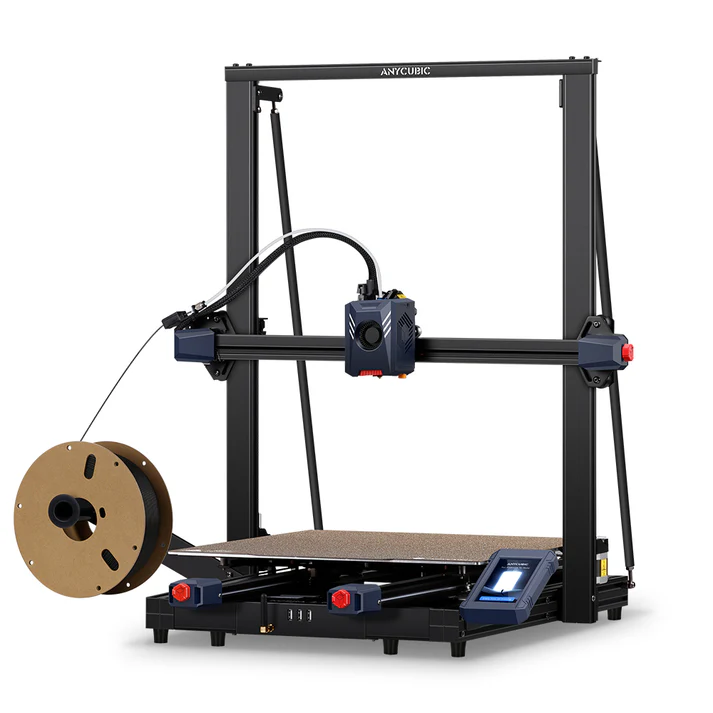

Sometime last year, I acquired the large-format 3d printer from Anycubic, the Kobra 2 Max. The intent was for large prints, jobs that I couldn’t handle on my aging Prusa MK3s. With a build volume of 420x420mm, this handles about 4x the volume. The hope was further efforts with life-size droids, perhaps some cos-play helmets, large terrain pieces, etc, and just an ability to print a bit faster.
However, that rapidly hit a snag as a result of the general build quality of the Kobra 2. Its fast and its large, that part is great. It is not reliable or accurate – at least for me – right out of the box. This doesn’t mean that it prints 10 or 20% off size, but if a part is one or two millimeters off, then it frequently isn’t functional in an assembly. For the droid builds, it wasn’t much of an issue at their scale, but many other projects ended up failing. As a result, it quickly became the forgotten tool in the workshop.
Sometime later, still having problems with quality, I reached out to M&M Prop Shop for some suggested and guidance. They had printed a recent project using the same printer, and very helpfully shared their profile with me for comparison. This made a major difference in the strength of the parts and gave me more confidence. It also inspired me to revise all my profiles to follow the same strategies. The key difference was in the number of walls and the infill. I had been using 2 walls since that was the default, and using heavy infill for strength, with adaptive cubic for the pattern. In my mind, this was the best combination of speed and strength. However, my mind was obviously confused, since a better option was the reverse – strengthen the walls and minimize the infill. As a result, I now print typically with 4 walls, and only 10% infill. For speed, I use very basic triangular infill. Most of the strength comes from the wall thickness itself, not the infill, but most of the print time comes from the infill patterns. By making these changes, the parts come out far thicker, take much less time, and saves material.
Unfortunately, although this notably improved the quality of the models, it didn’t help the second problem I was experiencing – adhesion to the build plate. The Kobra 2 comes with a factory PEI spring-steel sheet, which magnetically attaches to the bed. Visually, everything looks nearly perfect and flat. So naturally, when you set up the machine, a calibration and bed leveling is run, which automatically records any deviation in the bed flatness. All routine and standard.
What is not routine however is that the default profiles that come from Anycubic (and which I had been using and evolving) do not include a basic command to reference that bed leveling data. Basically, you level the bed automatically and then ignore all the results in each print. This works OK if the bed is perfectly flat, but if there is slight variation, you end up with high and low spots – which I have been fighting for months. The Z-adjustment helps some, but that is a fixed value for the full bed, so it doesn’t remove the problem, so areas still print high or low.
Online, there are a variety of tutorials and options to apply spacers and springs to the bed itself, allowing tensioning of screws to bend the bed slightly and force it into a flat configuration. This no doubt works, but from all the videos, it is time consuming, challenging, and requires more tools and pieces – something I was not eager to dig into. And it still doesn’t solve the basic flaw that the machine is ignoring its own bed-leveling routines.
A better solution is to instead add the simple gcode to the profile. Then, at the start of each print, it enables bed mesh leveling data, and adjusts the printing to match the bed (rather than adjusting the bed itself). This doesn’t require tools, takes only moments, and accomplishes the same results.
To modify your gcode, you need to enter the command “M420 S1” into your machine start gcode, specifically after the G28 command. There may be other options, but this worked in my case – I ran one print which failed, modified the gcode, and re-ran the same job with a clean success.
There were some references to using the “G29” command to do the same thing, but that one didn’t make any changes in my case, so I just used M420.
For reference, my full machine start gcode is as follows:
G90                                 ;Use absolute coordinates
M83                                 ;Extruder relative mode
M140 S[first_layer_bed_temperature] ;Set bed temp
M190 S[first_layer_bed_temperature] ;Wait for bed temp
M104 S180                           ;Set extruder temp to 180C
M109 S180                           ;Wait for extruder temp
G28                                 ;home - Move X/Y/Z to min endstops
M420 S1                             ;mesh bed leveling
G1 Z1                               ;Lift nozzle a bit
M104 S[first_layer_temperature]     ;Set extruder temp
M109 S[first_layer_temperature]     ;Wait for extruder temp
G92 E0                              ;Specify current extruder position as zero
G1 X5 Y5 Z0.25 F3000                ;Move to start of purge
G1 X180 Y5 Z0.25 E25 F1500          ;Extrude 25mm in a 5cm line.
G1 X200 Y5 Z0.25                    ;clear purge
G92 E0                              ;zero the extruded length again
M117
I did tweak it a bit previously, since I don’t like the filament to ooze while the initially operations are being done, so in my case it warms to 180 degrees, does all the homing actions, then separately heats to the target temperature before running a short purge line and starting to print.
Hopefully this can be a help to others and improve your printing quality. And perhaps help you avoid the extensive hacking process of the alternatives.